P7
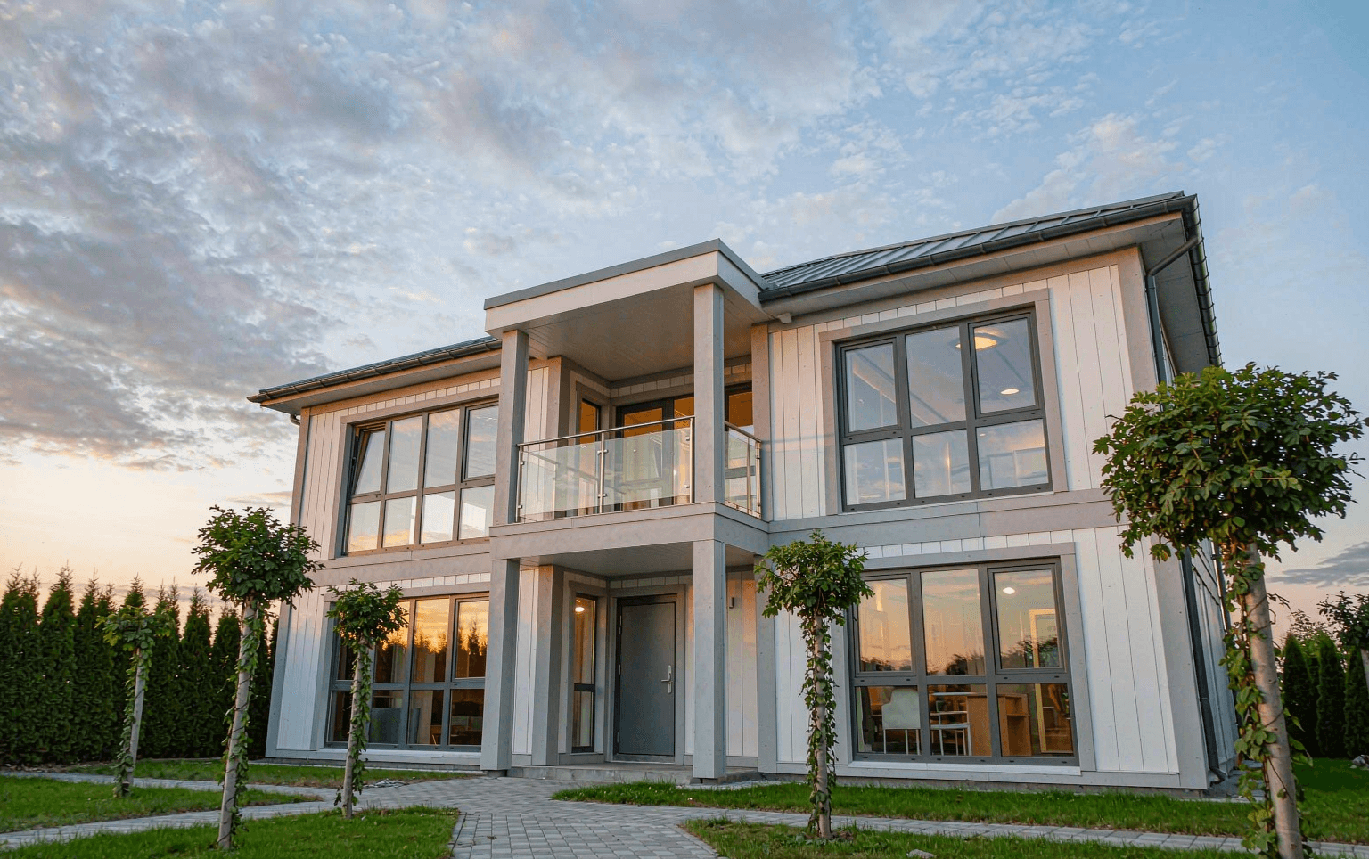
Light steel villa
Permanent housing · custom build or standard series
Overview
A permanent dwelling built on a cold-formed thin-wall steel (CFS) frame — wall studs, floor trusses and roof trusses roll-formed from galvanised steel strip, sheathed with board to act as a stressed skin. One product line, two configuration tracks: a custom layout designed for your plot, or a standard series that can be repeated, dismantled and re-erected.
Unlike container and prefab camp systems, the villa is designed to the destination building code, with plot-specific foundations, planning submission drawings and staged supply. Self-build housing, resort villas and staff housing are the main uses.
Configuration tracks
Both tracks use the same structural system and the same factory — the difference is who owns the design and how much is repeatable.
| Item | Custom build | Standard series |
|---|---|---|
| Design | One drawing set per dwelling, adapted to your plot | Fixed layout range, options list per series |
| Storeys | 1–2 storeys; 3 storeys on structural review | 1–2 storeys |
| Relocation | Normally not relocated | Can be dismantled, moved and re-erected |
| Interior | Fully bespoke | Standard package with options |
| Typical use | Private residence, resort villa, show home | Staff housing, resort clusters, phased community |
| Order size | 1 dwelling | Batch pricing from 10 dwellings |
| Decides on | Design capability and references | Unit cost, lead time, repeatability |
Technical data
| Parameter | Typical value | Notes |
|---|---|---|
| Structural system | Cold-formed thin-wall steel, C/U sections | Roll-formed from coil |
| Steel grade | Q345B or G550 galvanised / Al-Zn coated | Coating AZ150 / Z275 |
| Stud thickness | 0.75–1.8 mm (0.8–1.2 mm typical) | Upper range for load-bearing studs |
| Stud spacing | 400 mm / 600 mm | Matched to board module |
| Sheathing | OSB 12 / 16 / 18 mm | Provides diaphragm shear action |
| Wall build-up (out to in) | Cladding → breather membrane → XPS / rockwool → OSB → glass wool → plasterboard | Cladding: fibre cement, cultured stone or metal panel |
| Roof | Trusses + OSB + waterproof membrane + tile or metal sheet | Asphalt, stone-coated, clay or metal |
| Floor live load | 2.0 kN/m² (habitable) | By occupancy |
| Roof live load | 0.5 kN/m² (non-accessible) | Snow per project location |
| Design wind pressure | Per project location, e.g. 0.45 kN/m² | Cyclonic zones require specific review |
| Seismic | Checked for the project seismic intensity | Light mass, integrated frame |
| Design life | 50 years | Per project code |
| Reference standards | GB 50018; JGJ 227 (low-rise CFS housing) | Exported projects verified to destination code |
| Factory prefabrication | ≥90 %; site work is dry assembly | No wet trades on site |
| Self weight | Wall self weight approx. 1/5 of brick-concrete | Reduces foundation cost |
| Component tolerance | ±0.5 mm class | Or site re-drilling damages coating |
Structural system
Roll-formed C/U studs at 400 or 600 mm centres form the wall, floor-truss and roof-truss frames. Board sheathing on at least one face of each plane creates the diaphragm that carries lateral wind and seismic load — this stressed-skin action is why a 0.8 mm stud can carry a dwelling.
All framing is pre-punched, numbered and bundled to the erection sequence. Site work is bolting and screw-fixing, so tolerances do not depend on local concrete quality — the main reason this system suits overseas sites with limited local trades.
| Layer | Function | Typical |
|---|---|---|
| Foundation | Load transfer | Strip footing, raft or screw piles; lighter than masonry |
| Ground floor | Moisture control | Raised slab or suspended CFS floor with ventilated void |
| External wall | Envelope + shear | Board-sheathed stud wall with insulation within the frame |
| Intermediate floor | Tributary load | CFS floor trusses + OSB + acoustic fill |
| Roof | Slope + drainage | Trusses at 600–1200 mm, roof pitch per design |
| Services | Concealed routing | Services run inside the frame cavity |
Customization
For a permanent dwelling the layout, elevation and interior finish carry the value. These are the dimensions we need fixed before drawing sign-off.
| Dimension | Options | Notes |
|---|---|---|
| Floor plan | Studio / 2-bed / 3-bed / 4-bed; multi-unit blocks | Custom track only |
| Storeys | Single, two storey, with balcony or terrace | 3 storeys on structural review |
| Exterior style | Modern flat, pitched roof, Mediterranean, tropical, industrial | Drives cladding system choice |
| Cladding | Fibre cement board, cultured stone, metal panel, timber-look | Ventilated rainscreen recommended |
| Interior level | Shell only / standard / full fit-out | Kitchen and bathroom per local standard |
| Glazing | Aluminium or uPVC; single / double / Low-E | Match to climate zone |
| Roof finish | Asphalt shingle, stone-coated metal, clay, standing seam | Pitch must suit the chosen product |
| Optional scope | Solar PV, water tank, septic, borehole, fence, gatehouse | Quoted separately |
Typical models
Areas below are indicative of the standard series. Custom layouts are quoted from your own plan; total area and storey height are the two figures we need first.
| Code | Plan (m) | Floor area | Layout |
|---|---|---|---|
| V-30 | 5.0 × 6.0 | ~30 m² | Studio, 1 bath |
| V-50 | 7.0 × 7.2 | ~50 m² | 1 bed, living, 1 bath |
| V-80 | 8.0 × 10.0 | ~80 m² | 2 bed, living, 1–2 bath |
| V-120 | 10.0 × 12.0 | ~120 m² | 3 bed, living, 2 bath, terrace |
| V-160/2F | 8.0 × 10.0, 2 storey | ~160 m² | 4 bed, 2 bath, balcony |
| Custom | Per your drawing | Per drawing | Any layout within structural limits |
Delivery scope
Villa component count varies too much with layout, storey count and interior level to be stated as a fixed figure. Scope is therefore confirmed from the signed drawing, and the items below must be stated in the inquiry.
| Scope | Contents | Suits |
|---|---|---|
| KD kit (components) | Frame, sheathing, envelope, windows/doors, drawings, erection guide | Buyers with a local building crew |
| Semi-fitted | KD kit + ceiling, flooring, kitchen, sanitary, electrical rough-in | Common export scope |
| Turnkey (EPC) | Adds design, delivery, site supervision or dispatched crew | Government and resort projects |
Lead time
Reference: drawings 7–15 wd after information complete; production 30–45 days after drawing sign-off and deposit. Staged supply for multi-unit projects follows the contract batch plan.
Installation
Buyer: plot preparation, foundation, mains utilities and site access. Erection sequence: foundation anchors → ground floor frame → wall panels → floor trusses → upper walls → roof trusses → roofing → envelope → MEP → interior. Reference: main structure of 200–300 m² in 1–2 weeks with a trained crew, after the foundation is ready.
Dry assembly, no wet trades. The supervisor's drawing set and a numbered component list are supplied; on-site guidance or a dispatched crew can be quoted separately.
Selection guide
| Requirement | Recommended | Alternative |
|---|---|---|
| Permanent home, plot-specific design | P7 custom build | Local masonry |
| Repeatable staff housing, phased | P7 standard series | P4 welded container |
| Temporary camp, relocate in 2 years | P4 / P1 | P7 standard series |
| Garden or terrace room only | P8 glass sunroom | — |
| Planning approval is the main constraint | Confirm local rules first | P8 retractable |
Request specification
| Field | Description |
|---|---|
| Configuration track | Custom build or standard series (V-30 to V-160) |
| Floor area & storeys | Target m², single or two storey |
| Plot plan | Site dimensions, access and boundary if available |
| Exterior style & cladding | Reference images welcome |
| Interior level | Shell only / standard / full fit-out |
| Delivery scope | KD kit / semi-fitted / turnkey |
| Climate loads | Design wind and snow, coastal or cyclonic |
| Building code | Applicable building code if known |
Get a quote
Send floor area, storey count and interior level. We will return a configuration outline and the drawing schedule.
Typical specifications for reference only. Final dimensions, materials and quantities per signed drawings and order.